Fitting Frames (by T)
Figuring out the framing is making my head hurt. Chapelle doesn’t give any details about framing other than thickness of the timbers. Barto’s plans show approximate locations, but but they seem more like suggestions up for discussion. Not that it would make much difference if the plans were specific. The interiors are where these boats will most deviate from the plans anyway – centerboards instead of daggerboards, enlarged cockpits, a forward hatch – so the framing has to move around to accommodate the changes. Moving one thing seems to affect seven others. After hours of head scratching, there comes a point where you get the basics covered and have to just forge ahead and make it up as you go along.
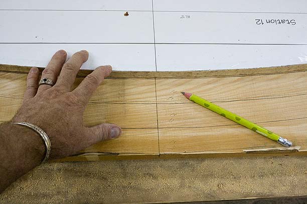
Once again, having the deck camber built into the molds is a gift that keeps on giving. Since positions of the frames are somewhat arbitrary, by studying the layout I realized most of the frames can be shifted and aligned directly over the original station locations. That means size and shape of those frames can be scribed directly from the molds. Nesting the molds makes for efficient use of the remaining Cypress planks, and easy since only the top curve edge of each frame is critical. Marking the centerline from the molds helps align them later.
Scribing Frames from the Molds
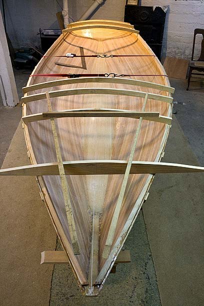
Once the first frames are cut, they can be moved around with additional scraps to get a feel for the final layout, shifting and noting locations for parts to come later. Before starting, though, I noticed that, even with sheer clamps installed, the hulls were falling open under their own weight by more than an inch. If I’d framed them this way, the decks, which are already made, would not have fit. So straps are cinched in around the hulls to hold the correct shape until framing is in place.
Oddly enough, having the staple holes still visible is really coming in handy, revealing the locations of the original mold stations and making them easy to find. Since many later elements reference these stations for relative position, actually being able to find them all the way around the hulls is a good thing. Trying to find them with a tape measure at this point would be all but impossible.
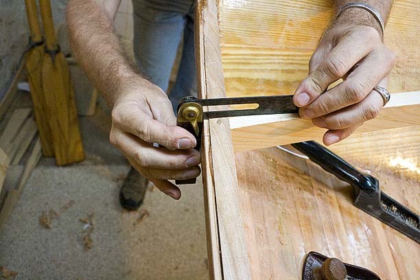
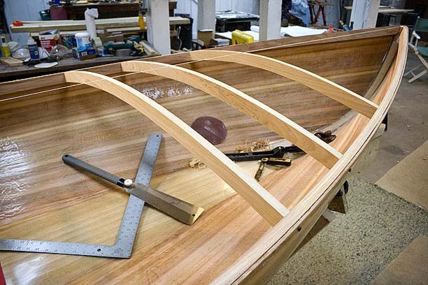
Aligned over a station, and centered under the string line, the frames can be rest on the sheer while they’re adjusted and squared to the string. Then the sheer clamp is marked, and a bevel gauge used to scribe the angles for cutting. The first cut is fat, and the frames are carefully shortened until the they slide in tight to the marks. The pull saw works great for this, but the final fit is easiest with the bench sander where the exact bevel can be set and small adjustments made. Some final fitting is done with the sanding disk trick used during stripping.
Once a frame is dry fit, the sheer clamp can be beveled to match the camber of the adjoining frame, planing it down to the edge of the hull. Terri snapped some nice shots of that in progress.
I have several tools handed down to me from my grandfathers, some from each, and using my grandfather’s Bevel Gauge and Block Plane for this stuff is a real pleasure, in ways a little hard to describe. The Bevel Gauge itself is a beautiful thing, made of Rosewood and Brass and Blued Steel. It’s so useful it stays in my pocket most of the time. And with a clean edge on the Plane, wood shavings curl up and away in thin semi-transparent slivers, like fresh Japanese ginger on a plate of sushi. What a difference from the noise and dust of my power tools, that seem bent on removing pieces of me along with the wood.
Matching the deck camber with Grandfather’s bevel gauge.
melonseed skiff, mellonseed skiff, melon seed, mellon seed


